Micro Switch KB encoding switches
Contents
Overview
Micro Switch KB included encoding switches. These are switches that encode their own output, avoiding the need for dedicated encoding circuitry. Micro Switch specifically state that this design “[eliminates] the cost and installation of diode matrices to encode the raw keyboard contact closures”. KB encoding switches contain 11 separate switch contacts, including eight for the output value. Each switch contact comprises three fine metal wires, giving triple redundancy.
KB encoding switches generate their identifying codes through an 11-way gang of contacts that includes one contact for each bit of the switch ID. Although considerable detail is given in the promotional material for encoding switches, and surplus parts are available for sale dated from 1966 to 1969 (indicating that they were in production), no details on specific models are given in the known catalogues.
The KB self-encoding switches were introduced in 1964; the KB reed switches were in 1965 or 1966. Micro Switch’s first keyboards were introduced around 1967, with “mechanical” switches (presumably KB self-encoding), with reed keyboards following later.
Operation
Each switch is assigned an 8-bit identity, which is enough to cover not just 7-bit ASCII but any other special keys required. When pressed, the key station generates this numeric ID directly without the need for any additional circuitry. These switches have a total of 12 terminals:
| Terminals | Function |
|---|---|
| 1 | Common |
| 2 | Strobe |
| 3–10 | Switch ID (0–255) |
| 11–12 | Electrical monitor |
The final two terminals are joined (and only have a single pair of contacts between them) and are used to determine when two switches are pushed simultaneously. As all switches share a common bus, there is no rollover, and the monitor wires detect collisions between buttons. The collision detection is not detailed, but a resistor is shown in the contact diagram (whose location is not disclosed or otherwise depicted), and that suggests that (based on what Mechanical Enterprises did) the resistance decreases with each concurrently active switch. As such, the current in that bus line will rise as each additional switch becomes active, allowing collisions to be detected.
To minimise problems with contact bounce, the strobe contacts close last. The strobe signal indicates that a key is active, and this signal is delayed to help ensure that the encoding contacts have settled before the keystroke is announced. Internally the contacts take this form, albeit in two rows, with six on one side and five on the other:
The diagram above is taken from Micro Switch’s own promotional material from the 1960s. A circuit diagram of the switch connected to the bus might look as follows:
Here, the electrical monitor resistor is drawn outside the switch, as there is no resistor visible within the switch itself. The exact nature of the electrical monitor is not specified.
Encoding switches remove the need for separate diode arrays to define the ID of each key. Instead, the key’s ID is set by clipping the tabs that connect to the switch terminals, to determine which bits on the connecting bus will be pulled low. Alternatively, the switch terminals themselves can be clipped. A photograph in the promotional material (see the KB documentation) shows a complete QWERTY keyboard with numeric keypad and function key row assembled using encoding switches, although such a keyboard has yet to be encountered.
The reason for having eleven separate pairs of contacts relates to the effect of having switches on a common bus. If the switches only had a single pair of contacts on the input terminal, the remaining terminals would be permanently connected to the bus. As soon as any switch started conducting, current would pass back into each inactive switch, through the common connections to their terminals, and back out onto the bus, jamming it. The result is that every terminal needs its own contacts, to prevent current entering other switches through their output terminals. Mechanical Enterprises took a different approach with their Mercutronic coding switches, placing a diode on every output terminal.
Design
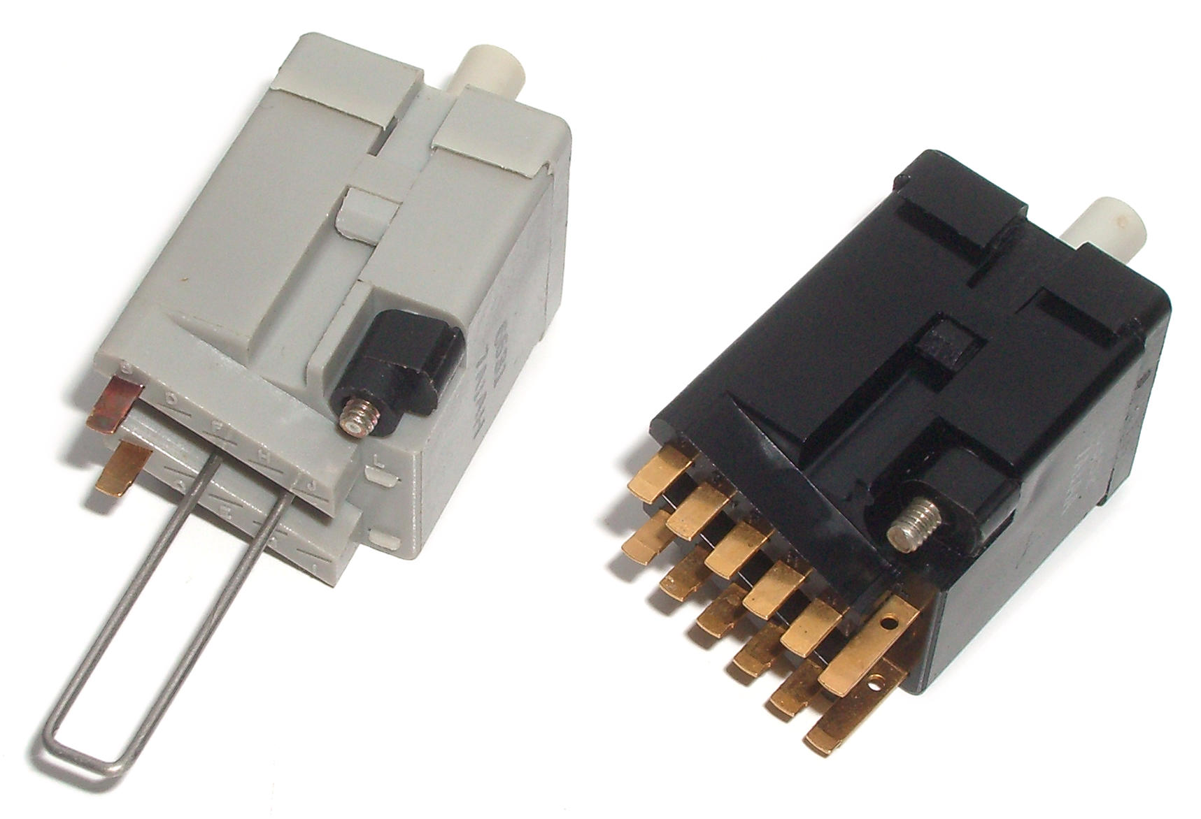
KB encoding switches use trifurcated contacts. The contact surface does not appear to be documented. From the colour, it may be silver plating. The movable contacts are all fixed the plunger and move with it, and they are all connected together. One contact set receives power, and this is passed to all the other contact sets. The stationary contacts are held in blocks that are slotted into the switch, six per block on each side. These appear to be gold-plated. Each stationary contact is in two halves, one above the other, with a small gap in between. This may be there to provide a consistent sliding surface for the contact prongs, but that does not explain why the inactive top halves also look to be gold plated.
The encoding switches appear to provide the same keycap mount as the reed switches. Model 7A1AH only has two terminals; no details are known for this or any other specific encoding switch models.
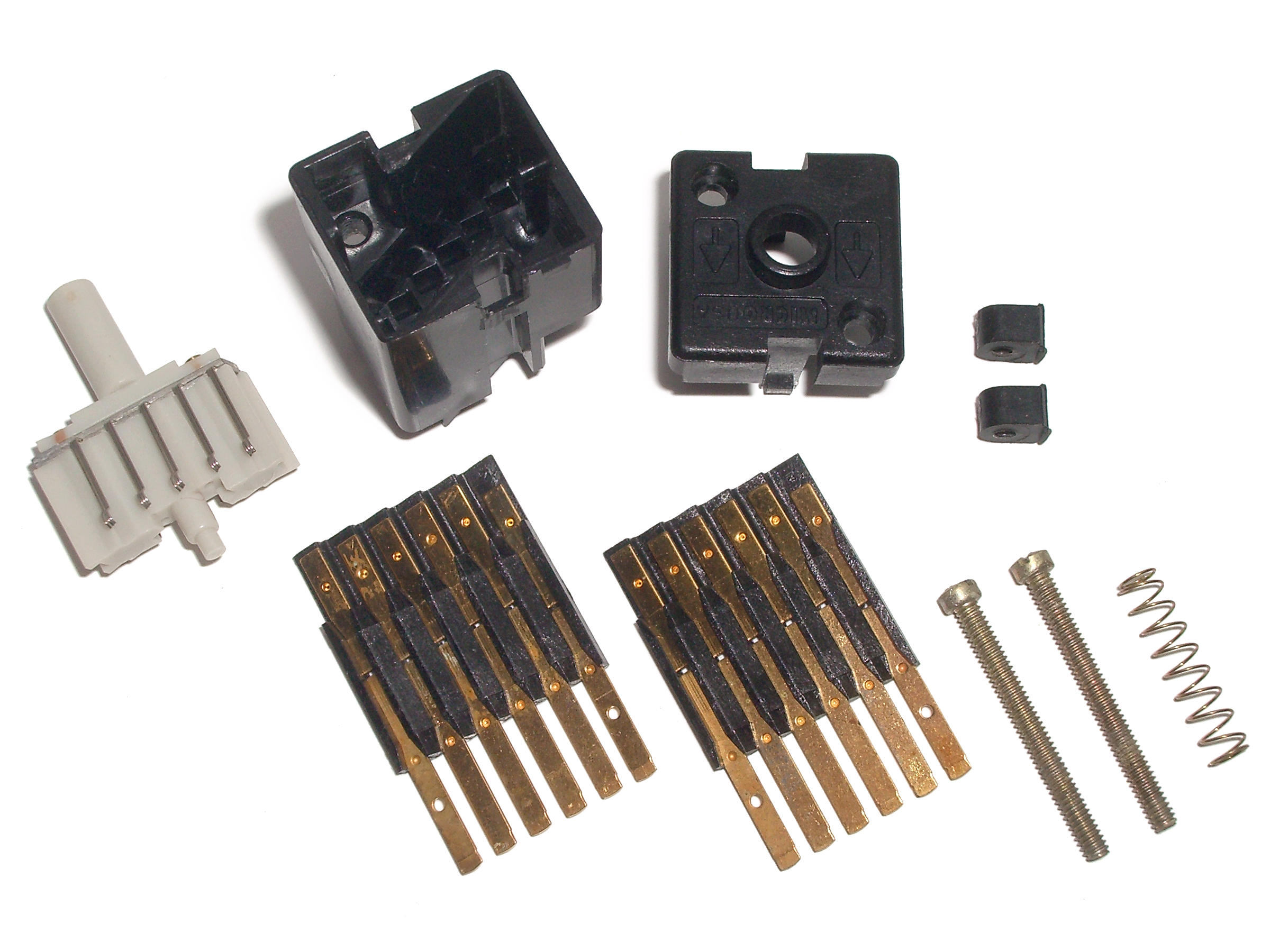 Internal parts of the switch
Models
The following types are not in the catalogue.
| Catalogue listing | Type |
|---|---|
| 7A1AA | Full encoding type |
| 7A1AH | Single pair of terminals, with interlock operating “trombone” plunger extension |
| 7A1AL | Not observed |
| 7A1AM | Not observed |
Disassembly
As with the reed types, the encoding switches come apart easily. However, reassembling them is difficult. Every contact pair has three delicate wires, and these readily snag on the contact block. Thus, the plunger has to be inserted first, and held down on its spring, while the contact blocks are slid into place either side of it. This is a tricky process but it can be done.
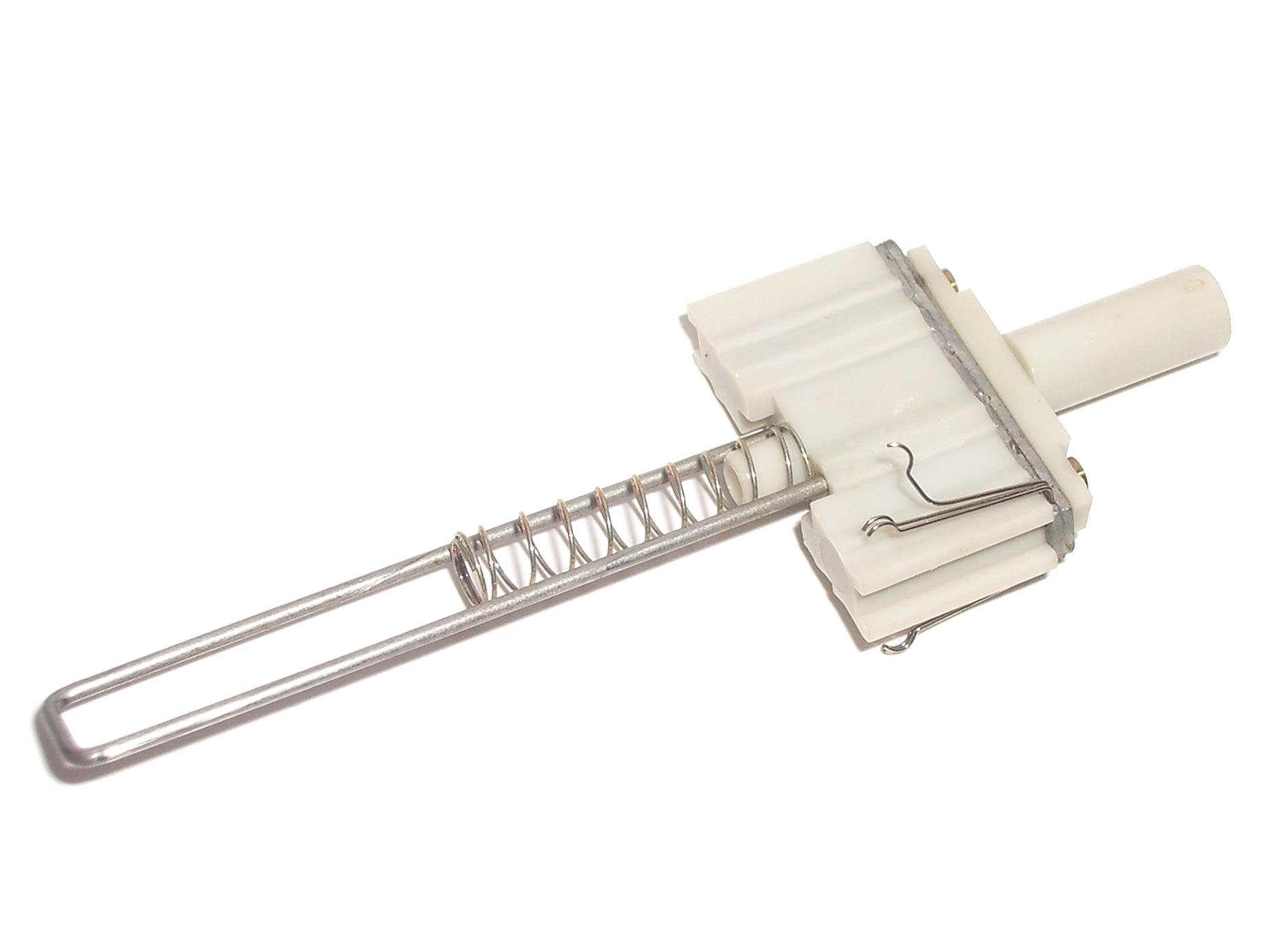 Damaged contact prong that got snagged during plunger reinsertion; fortunately this model only has two contact sets and the damage was limited and repairable
Documentation
See the main KB page for documentation.