Rannoch–Tummel–Abernethy towers
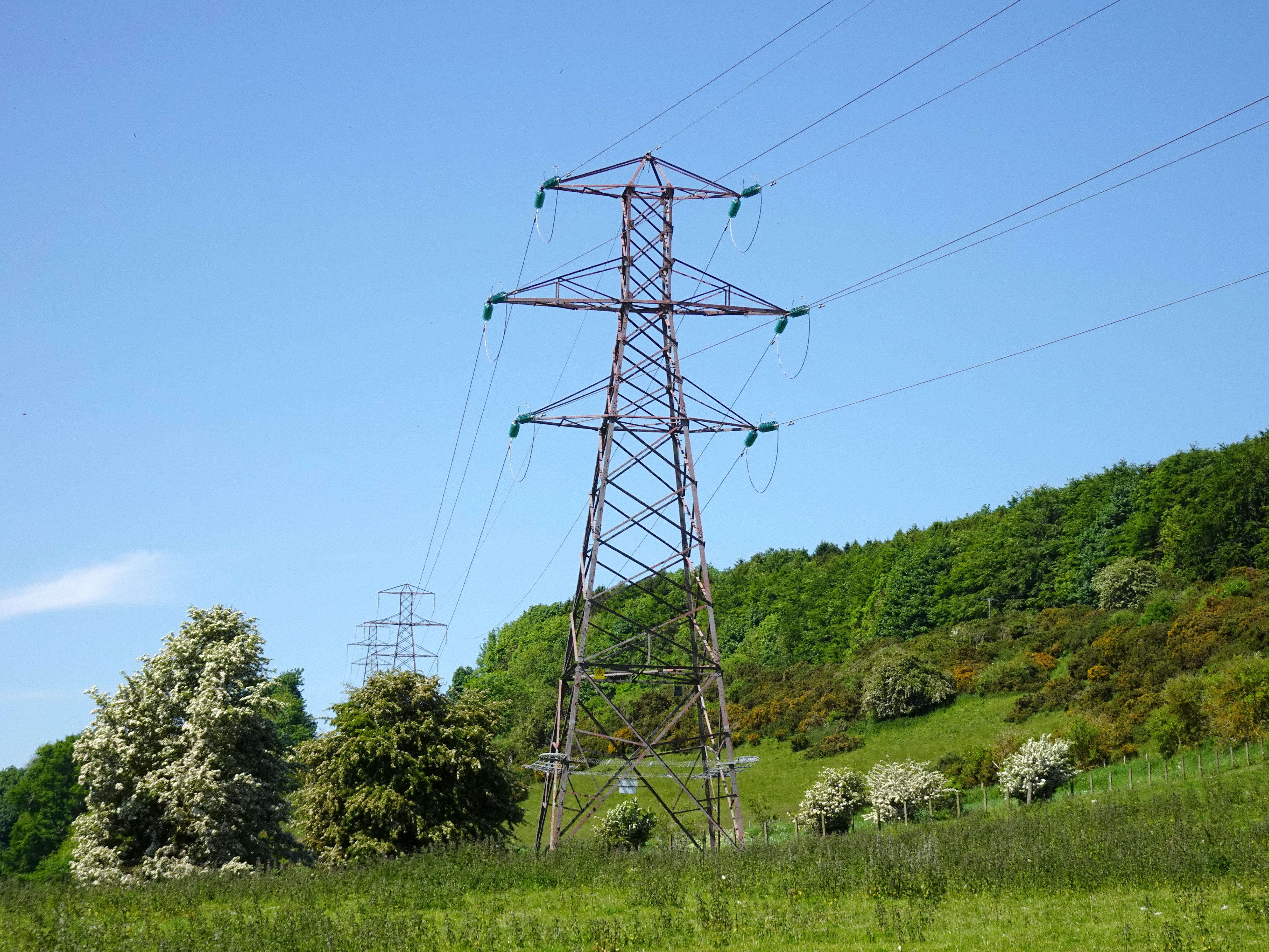
Photo courtesy Ian McAulay (CC-BY-NC)
Contents
Overview
This is a tower suite that appears to be unique to the line built for the Grampian Electricity Supply Company from Rannoch hydroelectric power station to Abernethy via Tummel Bridge, allegedly completed in 1930. Comparison between the 1945–47 Ordnance Survey map of Scotland and the Open Infrastructure Map shows that the line has been significantly altered since its original construction.
The first section of the line runs from Rannoch power station on the shore of Loch Rannoch, to Tummel Bridge power station; this section uses special four-circuit towers, capable of carrying double circuit 132 kV plus double circuit 33 kV. From Tummel Bridge the line is diverted to nearby Errochty switching station where it terminates; this brief section line is PL16 double circuit. The original alignment around Tummel Bridge is not clear from the OS map.
The second section of the line starts at Errochty switching station and terminates at Abernethy substation. The first part of this line has been replaced by a combination of J L Eve C670 line towers and PL16 angle towers; it does not follow the original route, which has since been taken (to some extent) by the new Beauly–Denny line. There is then a substantial diversion east, passing by Griffin Wind Farm. Griffin Wind Farm is a modern facility constructed in 2010, seemingly too modern for the Eve and PL16 towers used on the diversion. Part of the line leading up to the diversion is now undergrounded. Beyond the diversion, at a location somewhere in between Amulree and Buchanty, the line changes to the original “Rannoch–Abernethy” towers, and the line continues as such to its terminus at Abernethy substation.
General data
| Designed for | Grampian Electricity Supply Company |
|---|---|
| Design contractor | A & J Main & Co |
| Found | |
| Height (straight line tower) | 79′–3″ (24.2 m) (double circuit) |
| Voltage |
132 kV 132 kV + 33 kV |
| Conductors | Single |
| Circuit count |
Double (2 × 132 kV) Four (2 × 132 kV + 2 × 33 kV) |
| Design conductor | Unknown |
| Normal span | Unknown |
Progress
| Diagram coverage | Good |
|---|---|
| Diagram source | Various |
| Drawings needed | All except “S” and “M” A |
| Photo coverage | Good |
| Information needed |
|
Tower types
As with Tummel Bridge–Keith, the smaller angle tower is tentatively suggested to be 20° deviation rather than 30° deviation. Unlike Tummel–Keith, there are few examples to work from, not least due to the amount of tower replacement. There is a larger angle tower at Buchanty (56.435° N 3.734° W) with a deviation of only 23.5°. There is another such tower near Abernethy (56.338° N 3.338° W) with a 25° deviation; although the next two towers in the direction of Abernethy substation are PL16 D10, this deviation is exactly as shown on the 1945–47 Ordnance Survey map of Scotland. The same pattern exists with the dual voltage towers: deviations above around 20° use the larger size angle towers.
Lines
- Rannoch power station to Errochty switching station (three circuits, on four-circuit towers)
- Errochty switching station to Abernethy substation (double-circuit)
Tower forms
Double circuit
Tummel to Abernethy towers, double circuit 132 kV. The diagrams for “S” and “M” A are to scale at 12 pixels per metre. The transposition tower diagram is a combination of the “M” A tower and the transposition tower crossarms traced from Google Street View. The heavier angle tower diagram is entirely derived from Street View, scaled to the “M” A tower.
Four circuit
The diagrams below are derived solely from Google Street View imagery, scaled approximately to SWE PL1 (SS-PL1). The actual towers are smaller than predicted, but the diagrams below have not been rescaled to correspond with the only known drawings (“S” and “M” A).
Double circuit 132 kV plus double circuit 33 kV:
From Google Street View there is no complete ground-level, straight-on view of the “angle 2” tower, so some of the details are less accurate than the other drawings. There are two quad-circuit transposition towers between Rannoch and Tummel Bridge (one is just behind the Loch Rannoch Hotel and Estate, 56.703° N 4.206° W, the other at 56.691° N 4.340° W), but neither one can be seen clearly from Street View, so this diagram is only very approximate.
The four-circuit line tower is drawn as full quad circuit as per the tower’s design (four sets of insulators), although at present only one 33 kV circuit is populated.
The strange vertical rods up the face of each tower carry step bolts. This may be due to the proximity of one of the 33 kV phases to the tower body. The same central step bolt arrangement can be found on a US dual-voltage type used in Missouri, for example the tower found at 13136 Big Bend Road in St Louis.
Examples
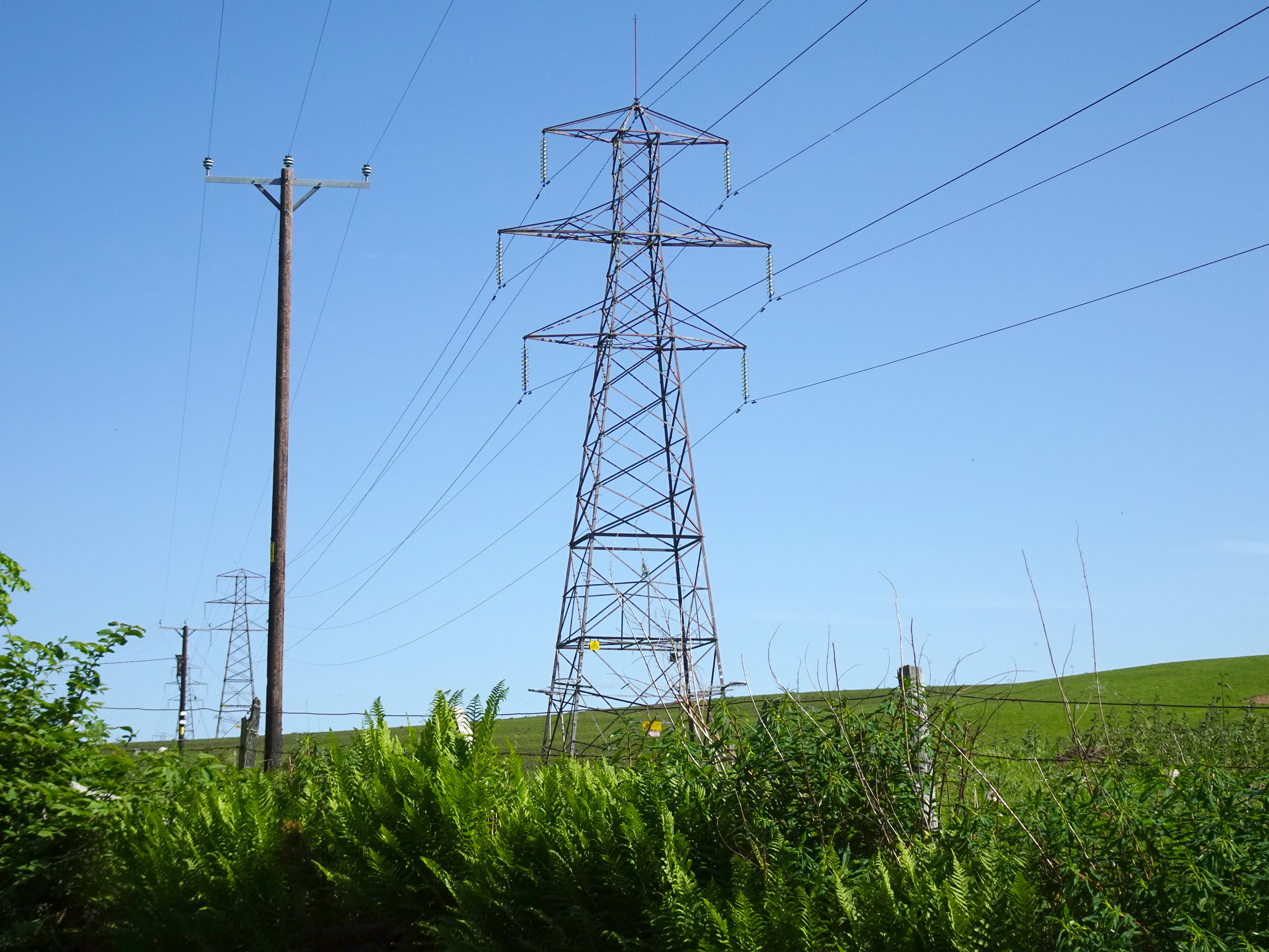
Photo courtesy Ian McAulay (CC-BY-NC)
Photo courtesy Ian McAulay (CC-BY-NC)
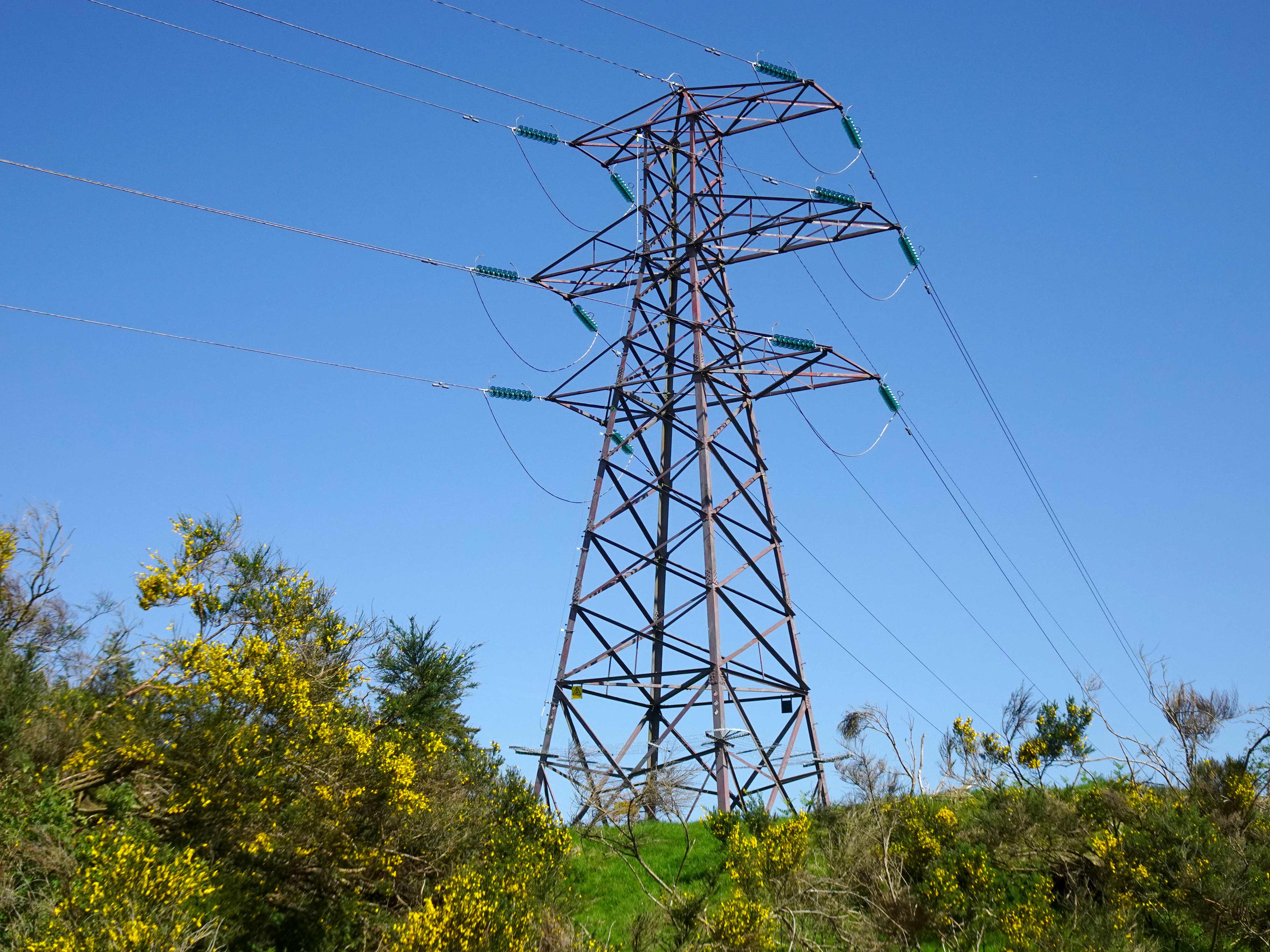
Photo courtesy Ian McAulay (CC-BY-NC)
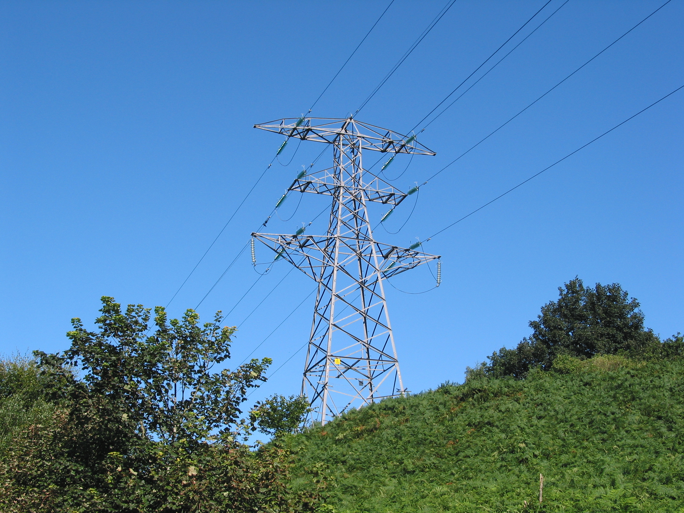
Photo courtesy Ian McAulay (CC-BY-NC)
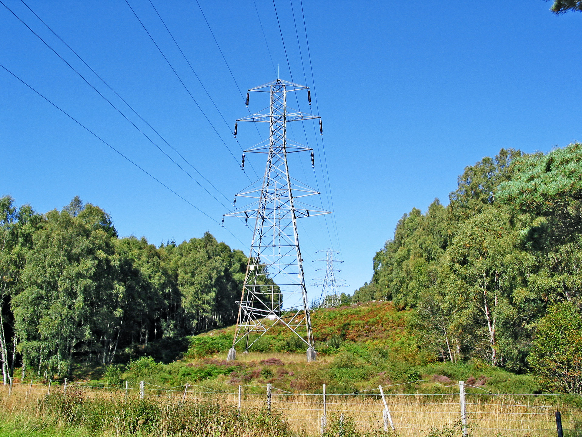
Photo courtesy Ian McAulay (CC-BY-NC), colours corrected
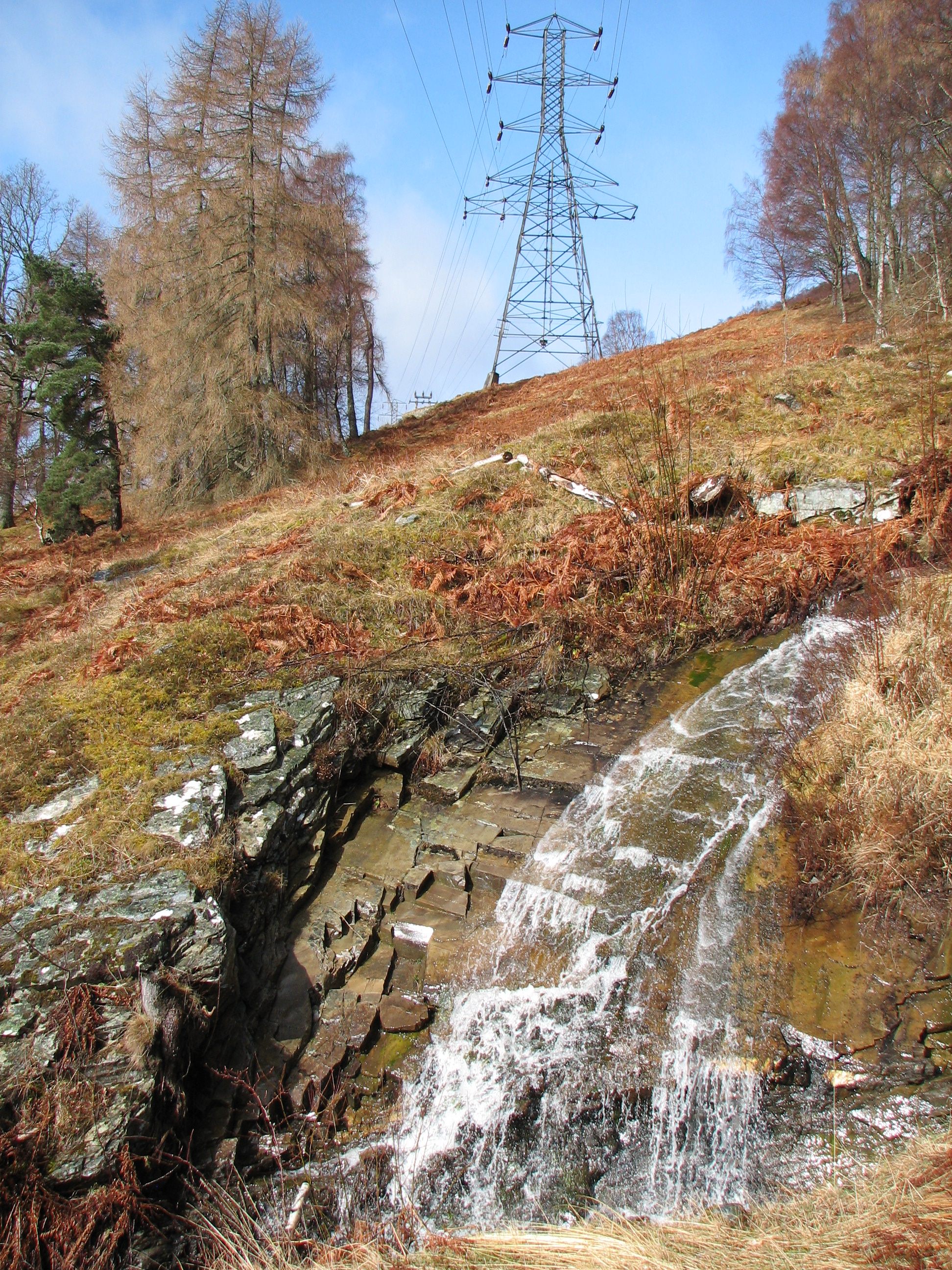
Photo “Pylons and stream” © Callum Black (CC-BY-SA 2.0); cropped
The transposition tower is said to be long since demolished.
Tower details
See dimensions on the site guide page for a key to the tables.
| Type | Source | Height | Base width | Overall width |
|---|---|---|---|---|
| “S” | 525/1109/1038 AKA /1056 | 79′–3″ (24.2 m) | 19′–0″ (5.8 m) | 31′–6″ (9.6 m) |
| “M” A | 525/1109/1039 | 72′–0″ (21.9 m) | 19′–0″ (5.8 m) | 30′–4″ (9.2 m) |
| Tower type | Peak to top crossarm | Top to middle crossarm | Middle to bottom crossarm | Bottom crossarm to ground |
|---|---|---|---|---|
| “S” | 4′–0″ | 12′–0″ | 12′–0″ | 51′–3″ |
| “M” A | 4′–0″ | 12′–0″ | 12′–0″ | 44′–0″ |
525/1109/1038 and 525/1109/1056 are the same drawing; the A & J Main tracing number is unclear but seems to be 15.116E.
See also
- Grampian Power Supply Company album (Flickr)
- Dual voltage towers, alternative photograph (Alamy)
- A. & J. Main & Co., Ltd., Industrial Britain (1930), Grace’s Guide, depicting an “S” tower prior to stringing